 English
 Español
 Português
 русский
 français
 日本語
日本語 Deutsch
 Tiếng Việt
 Italiano
 Nederlands
 ไทย
ไทย Polski
 한국어
한국어 Svenska
 magyar
 Malay
Malay বাংলা
বাংলা Dansk
Dansk Suomi
Suomi हिन्दी
 Pilipino
 Türk
Türk Gaeilge
 عربى
عربى Indonesia
 norsk
norsk Burmese
 български
 ລາວ
ລາວ Latine
 Қазақ
Қазақ Euskal
 Azərbaycan
 slovenský
 Македонски
 Română
 Slovenski
 Српски
 Afrikaans
 Беларус
 Hrvatski
 Монгол хэл
 Zulu
Zulu Somali
 O'zbek
 Hawaiian
ORIENT Photorelay Introduction
ORIENT Photorelay Introduction
Ray Wang [email protected] www.orient-opto.com
1, Product Introduction:
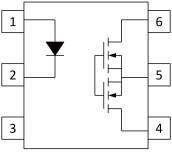
The structure of the photorelay: In the case of the ORIENT OR-440AS, the input side of the photorelay is equipped with an infrared led, and the output side is equipped with a photodiode array (hereinafter referred to as "PVG") and MOSFETs. Figure 1 shows an example of the internal structure of the 2.54SOP4 package, which is one of the photorelay unfolded packages. The LED on the input side and the PVG on the output side are placed face to face and are insulated with resin.

Figure 1.
The working principle of the photoelectric relay OR-440A. The photorelay works by applying a current to the LED on the input side. The PVG on the output side then receives the infrared light from the LED, generating the electromotive force. This electromotive force drives the connected MOSFET gate, which opens the MOSFET.
The contact structure of optical relay form A is contact type, and the output side opens when a certain amount of current is applied to the input side. This contact type is also called normally open type. Denoted as 1a, denotes the 1-pole a contact relay and the 2-pole a contact relay, denoted as 2a. On the other hand, when a certain amount of current is applied to the input side, the output side of the form B contact type remains closed, and when the input current is below a certain level, the output side turns on. This type of contact is also known as normally closed contact. Denotes 1 pole b contact relay, denoted 1b; 2-pole b contact relay, marked 2b. The photorelay A uses an enhanced MOSFETs and the photoelectric relay B uses a depletion MOSFETs.

Figure 2.
2,The application
1). The ORIENT Photorelay function is used in the circuit to monitor the charging voltage of the battery unit. The relay is expected to produce many contacts, and photoelectric relays are highly recommended because they do not have such a concept as contact life (long life). Advantages: Small size, long life, high withstand voltage.

Figure 3. From TOSHIBAPhotorelay E-book(Replacement for mechanical relay)page64
2). The ORIENT Photorelay is used as a switch for the light and sound output of camera sets. Advantages No noise, long life, small size

Figure 4. From TOSHIBAPhotorelay E-book(Replacement for mechanical relay)page64
3). ORIENT Photorelay is used to monitor insulation deterioration of battery cells. If the insulation in the unit deteriorates, when the relay is switched on, the ground fault current passes through and the sensor detects the current. The high load voltage type Photorelay is the ideal high voltage battery.

1.The circuit principle:

High response speed

4.Typical model
ORIENT SOP4
 |
1. Anode 2. Cathode 3.4. Drain |

|
Product |
Output type |
Load Voltage (V) |
Load Current (mA) |
Ron Typ. (Ω) |
Ifon max. (mA) |
Viso (Vrms) |
|
ORM406A |
Normally Open 1 Form A |
60 |
550 |
2 |
3 |
3750 |
|
ORM406A-16 |
Normally Open 1 Form A |
60 |
1600 |
0.5 |
3 |
3750 |
|
ORM410A |
Normally Open 1 Form A |
100 |
250 |
1 |
3 |
3750 |
|
ORM425A |
Normally Open 1 Form A |
250 |
180 |
9 |
3 |
3750 |
|
ORM440A |
Normally Open 1 Form A |
400 |
150 |
20 |
3 |
3750 |
|
ORM460A |
Normally Open 1 Form A |
600 |
100 |
40 |
3 |
3750 |
ORIENT DIP4
|
1. Anode 2. Cathode 3.4. Drain |

|
Product |
Output type |
Load Voltage (V) |
Load Current (mA) |
Ron Typ. (Ω) |
Ifon max. (mA) |
Viso (Vrms) |
|
OR406A |
Normally Open 1 Form A |
60 |
550 |
2 |
3 |
5000 |
|
OR406A-16 |
Normally Open 1 Form A |
60 |
1600 |
0.5 |
3 |
5000 |
|
OR410A |
Normally Open 1 Form A |
100 |
250 |
1 |
3 |
5000 |
|
OR425A |
Normally Open 1 Form A |
250 |
180 |
9 |
3 |
5000 |
|
OR440A |
Normally Open 1 Form A |
400 |
150 |
20 |
3 |
5000 |
|
OR460A |
Normally Open 1 Form A |
600 |
100 |
40 |
3 |
5000 |
ORIENT SMD5
 |
1. Anode 2. Cathode 4. Drain 6. Drain |

|
Product |
Output type |
Load Voltage (V) |
Load Current (mA) |
Ron Typ. (Ω) |
Ifon max. (mA) |
Viso (Vrms) |
|
ORAQV258HP5S |
Normally Open 1 Form A |
1700 |
50 |
10 |
3 |
5000 |
|
ORAQV258HP5S-SJ |
Normally Open 1 Form A |
1700 |
50 |
70 |
3 |
5000 |
|
ORAQV258LP5 |
Normally Open 1 Form A |
1500 |
20 |
150 |
3 |
5000 |
ORIENT SO16
 |
4:Anode 5:Cathode 6:Anode 9:Drain 10:Drain 15:Drain 16:Drain |

|
Product |
Output type |
Load Voltage (V) |
Load Current (mA) |
Ron Typ. (Ω) |
Ifon max. (mA) |
Viso (Vrms) |
|
OR601J |
Normally Open 1 Form A |
1500 |
50 |
50 |
3 |
5000 |
Ray Wang [email protected] www.orient-opto.com
Revolutionizing Signal Isolation: The Rise of Phototransistor Optocouplers in Modern Electronics
In the rapidly evolving landscape of industrial automation and consumer electronics, the demand for reliable signal integrity and circuit protection has never been higher.
Read MoreHow Do You Test a Photoelectric Sensor? Industry Experts Share Best Practices for Reliable Automation
As factories, warehouses, and smart systems increasingly rely on automation, the performance of photoelectric sensors has become critical to maintaining smooth operations. These sensors are widely used for object detection, counting, positioning, and safety monitoring. With their growing importance, a key question among technicians and maintenance teams is: How do you test a photoelectric sensor to ensure it is functioning correctly?
Read MoreWhat Are the Advantages of Photoelectric Detectors? Growing Demand Reflects Their Rising Role in Modern Automation
As global industries push for smarter, faster, and more automated operations, photoelectric detectors have become one of the most widely adopted sensing technologies in manufacturing, logistics, transportation, and smart devices. Their ability to detect objects without physical contact has made them essential in applications where precision, speed, and reliability are critical.
Read More