 English
 Español
 Português
 русский
 français
 日本語
日本語 Deutsch
 Tiếng Việt
 Italiano
 Nederlands
 ไทย
ไทย Polski
 한국어
한국어 Svenska
 magyar
 Malay
Malay বাংলা
বাংলা Dansk
Dansk Suomi
Suomi हिन्दी
 Pilipino
 Türk
Türk Gaeilge
 عربى
عربى Indonesia
 norsk
norsk Burmese
 български
 ລາວ
ລາວ Latine
 Қазақ
Қазақ Euskal
 Azərbaycan
 slovenský
 Македонски
 Română
 Slovenski
 Српски
 Afrikaans
 Беларус
 Hrvatski
 Монгол хэл
 Zulu
Zulu Somali
 O'zbek
 Hawaiian
ORIENT IGBT Drive Optocoupler Product Introduction
ORIENT IGBT Drive Optocoupler Product Introduction
Ray Wang [email protected] www.orient-opto.com
1. IGBT Introduction:
IGBT, short for Insulated Gate Bipolar Transistor, is a high-power semiconductor device commonly used in power electronics applications, especially for circuits with high voltage and current. The IGBT combines the high input impedance of a MOSFET (metal oxide semiconductor field-effect transistor) with the voltage-driven characteristics of a GTR (power transistor).
The IGBT is a three-terminal device: gate, collector and emitter.
IGBT symbol: 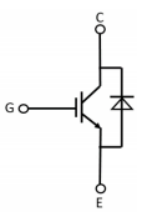 IGBT equivalent circuit:
OR-341W
2, ORIENT IGBT drive optocoupler introduction:
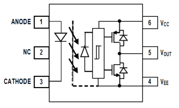
The ORIENT IGBT isolated drive optocoupler consists of an LED coupled to an integrated circuit with a power output stage. This optocoupler is ideal for power IGBTs and MOSFETs used in drive motor and inverter applications. The high operating voltage range at the output provides the drive voltage required by the gate control device.
3, General application of ORIENT IGBT drive optocoupler:
1), IGBT/MOSFET gate drive
2), AC/brushless DC motor driver
3), Inverter
4), Switching power supply
4,ORIENT IGBT drive optocoupler electrical parameter interpretation:
1), Forward working voltage-VF: refers to the voltage drop of the LED itself at a given working current;
2), Reverse voltage-VR: refers to the LED withstand the maximum reverse voltage, more than this reverse voltage, may damage the LED;
3), Input threshold current-IFLH: refers to the optocoupler input trigger current, reach this current, the optocoupler can be normally switched on;
4), Closing threshold voltage-VFHL: refers to the optocoupler input closed threshold voltage, below this voltage, the optocoupler closed does not work;
5), High level output peak current-IOPH: refers to the output port VO can output the maximum peak current;
6), Low level output peak current-IOPL: refers to the maximum peak current that VO can flow into the output port at low power level;
7), High level power supply current-ICCH: refers to the output no-load, and output high voltage, the power supply PT current, its size marks the size of the device static power consumption;
8), Low level power supply current-ICCL: refers to the output no-load, and output low voltage, the power supply PT current, its size marks the size of the device static power consumption;
9),High level output voltage-VOH: refers to the voltage value of the output port VO at high power level;
5,ORIENT IGBT Drive optocoupler Typical models:
ORIENT's current IGBT drive optocoupler covers package shapes: 8PIN, SO6, SOP5


8PIN Package SO6 Package SOP5 Package
The ORIENT IGBT drive optocoupler can also be distinguished by VCC supply voltage and IO(PEAK) output peak current:
| VCC operating voltage 15-30V | Output peak current 1A | Output peak current 1.5A | Output peak current 3A | Output peak current 4A |
| OR-340 | OR-3150 | OR-3120 | OR-343 | |
| OR-341 |
| VCC operating voltage | 10-30V Output peak current 1A | Output peak current 1.5A | Output peak current 2.5A | Output peak current 3A |
| OR-155E | OR-314 | OR-152 | OR-250H |
When recommending to customers, pay attention to the VCC power supply conditions used by customers.
6, Typical application circuit of ORIENT IGBT drive optocoupler:
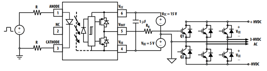
1), Input switch signal at the IR end of the primary side, working current IF generally recommended to use 7mA-16mA.
2), The sub-side VCC end can choose 15V-30V and 10V-30V corresponding power supply conditions according to the different power supply conditions of the two VCC types of IGBT drive optocoupler.
3), The VEE end of the sub-side is generally 0V or gives a certain negative pressure.
4), Connect a 1uf or 0.1uf bypass capacitor between the VCC end and the VEE end on the secondary side.
5), The sub-side VO output end needs to be connected to a gate resistor Rg, and then connected to the gate of the IGBT, the smaller Rg can charge and discharge the IGBT input capacitor faster, thereby shortening the switching time, but the smaller Rg will lead to the IGBT input capacitance and parasitic inductance oscillation, the general Rg design is used between 10Ω and 47Ω.
Ray Wang [email protected] www.orient-opto.com
How Do You Test a Photoelectric Sensor? Industry Experts Share Best Practices for Reliable Automation
As factories, warehouses, and smart systems increasingly rely on automation, the performance of photoelectric sensors has become critical to maintaining smooth operations. These sensors are widely used for object detection, counting, positioning, and safety monitoring. With their growing importance, a key question among technicians and maintenance teams is: How do you test a photoelectric sensor to ensure it is functioning correctly?
Read MoreWhat Are the Advantages of Photoelectric Detectors? Growing Demand Reflects Their Rising Role in Modern Automation
As global industries push for smarter, faster, and more automated operations, photoelectric detectors have become one of the most widely adopted sensing technologies in manufacturing, logistics, transportation, and smart devices. Their ability to detect objects without physical contact has made them essential in applications where precision, speed, and reliability are critical.
Read MoreHow Long Do Photoelectric Sensors Last? Industry Reports Highlight Impressive Lifespan and Reliability
As automation continues to reshape manufacturing, logistics, and smart infrastructure, photoelectric sensors have become essential components for reliable detection and control. With widespread adoption across industries, a frequent question from engineers and buyers is: How long do photoelectric sensors last?
Read More