English
 English
 Español
 Português
 русский
 français
 日本語
日本語 Deutsch
 Tiếng Việt
 Italiano
 Nederlands
 ไทย
ไทย Polski
 한국어
한국어 Svenska
 magyar
 Malay
Malay বাংলা
বাংলা Dansk
Dansk Suomi
Suomi हिन्दी
 Pilipino
 Türk
Türk Gaeilge
 عربى
عربى Indonesia
 norsk
norsk Burmese
 български
 ລາວ
ລາວ Latine
 Қазақ
Қазақ Euskal
 Azərbaycan
 slovenský
 Македонски
 Română
 Slovenski
 Српски
 Afrikaans
 Беларус
 Hrvatski
 Монгол хэл
 Zulu
Zulu Somali
 O'zbek
 Hawaiian

 Consume Grade Phototransistor Optocoupler OR-3H7-EN-V13
 Consume Grade Phototransistor Optocoupler OR-3H7-4-EN-V3
 Consume Grade Phototransistor Optocoupler OR-3H4-EN-V12
 Consume Grade Phototransistor Optocoupler OR-3H4-4-EN-V3
 Consume Grade Phototransistor Optocoupler ORPC-817-S-(SJ)
- Consume Grade Phototransistor Optocoupler ORPC-817-S-(SJ)-EN-V0
- All new products


Consume Grade Phototransistor Optocoupler ORPC-817-S-(SJ)-EN-V0
ORPC-817-(SJ) photo coupler consist of one piece of GaAs emitter and one piece of NPN transistor.
Product Description
silicon phototransistor
Features
- Current transfer ratio ( CTR : MIN. 50% at IF = 5mA, VCE = 5V )
- High input-output isolation voltage ( Viso = 5,000Vrms )
- Response time ( tr : TYP. 4µs at VCE = 2V, IC = 2mA, RL = 100Ω)
- ESD pass HBM 8000V/MM 2000V
- Safety approval
- UL approved (No.E323844) VDE approved(No.40029733)
- CQC approved (No.CQC09001029446) CE approved (No.AC/0431008)
- State Grid approved (No.SGCM013420170152 )
- In compliance with RoHS, REACH standards
- MSL Class Ⅰ
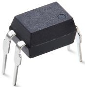
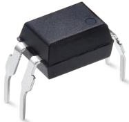
Description
ORPC-817-(SJ) photo coupler consist of one piece of GaAs emitter and one piece of NPN transistor.
Packaged in a 4-pin DIP package and available in wide-lead spacing option.
Applications
Switching power supply
Ammeter
Computer
Instrumental application, measurement machine
Signal transforming systems
Imbursement equipments, duplicating machine, automat
Family-use electric equipments, such as fans
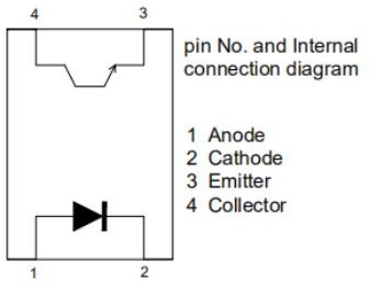
Functional Diagram
Absolute Maximum Ratings at Ta=25℃
|
Parameter |
Symbol |
Rated Value |
Unit |
|
|
Input |
Forward Current |
IF |
60 |
mA |
|
Peak forward Current (100μs pulse, 100Hz frequency) |
IFP |
1 |
A |
|
|
Reverse Voltage |
VR |
6 |
V |
|
|
Consume Power |
P |
70 |
mW |
|
|
Output |
Collector and emitter Voltage |
VCEO |
80 |
V |
|
Emitter and collector Voltage |
VECO |
7 |
||
|
Collector Current |
IC |
50 |
mA |
|
|
Consume Power |
PC |
150 |
mW |
|
|
Total Consume Power |
Ptot |
200 |
mW |
|
|
*1 Insulation Voltage |
Viso |
5,000 |
Vrms |
|
|
Max Insulation Voltage (Insulating oil test) |
VIOTM |
10,000 |
V |
|
|
Rated Impulse Insulation Voltage |
VIORM |
850 |
V |
|
|
Working Temperature |
Topr |
-55 to + 110 |
℃ |
|
|
Deposit Temperature |
Tstg |
-55 to + 125 |
||
|
*2 Soldering Temperature |
Tsol |
260 |
||
*1.AC For 1 Minute, R.H. = 40 ~ 60%
Isolation voltage shall be measured using the following method.
-
- Short between anode and cathode on the primary side and between collector and emitter onthe secondary side.
- The isolation voltage tester with zero-cross circuit shall be used.
- The waveform of applied voltage shall be a sine wave.
*2. Soldering time is 10 seconds
Electro-Optical Characteristics (Ta=25℃ unless specified otherwise)
|
Parameter |
Symbol |
Min |
Typ.* |
Max |
Unit |
Condition |
|
|
Input |
Forward Voltage |
VF |
--- |
1.2 |
1.4 |
V |
IF=20mA |
|
Reverse Current |
IR |
--- |
--- |
5 |
μA |
VR=5V |
|
|
Collector Capacitance |
Ct |
--- |
30 |
250 |
pF |
V=0, f=1KHz |
|
|
Output |
Collector to Emitter Current |
ICEO |
--- |
--- |
100 |
nA |
VCE=20V, IF=0mA |
|
Collector and Emitter attenuation Voltage |
BVCEO |
80 |
--- |
--- |
V |
IC=0.1mA IF=0mA |
|
|
Emitter and Collector attenuation Voltage |
BVECO |
7 |
--- |
--- |
V |
IE=0.1mA IF=0mA |
|
|
Transforming Characteristics |
*1 Current conversion ratio |
CTR |
50 |
--- |
600 |
% |
IF=5mA VCE=5V |
|
Collector Current |
IC |
2.5 |
--- |
30 |
mA |
||
|
Collector and Emitter Saturation Voltage |
VCE(sat) |
--- |
0.1 |
0.2 |
V |
IF=20mA IC= 1mA |
|
|
Insulation Impedance |
Riso |
5×10¹⁰ |
1×10¹² |
--- |
Ω |
DC500V 40~60%R.H. |
|
|
Floating Capacitance |
Cf |
--- |
0.6 |
1.0 |
pF |
V=0, f=1MHz |
|
|
Cut-off Frequency |
fc |
--- |
80 |
--- |
kHz |
VCE=5V, IC=2mA RL=100Ω,-3dB |
|
|
Rise Time |
tr |
--- |
4 |
18 |
μs |
VCE=2V, IC=2mA RL=100Ω |
|
|
Descend Time |
tf |
--- |
3 |
18 |
μs |
||
*1 Current Conversion Ratio = IC / IF × 100% , CTR Tolerance:±3%.
Rank Table of Current Transfer Ratio
|
CTR Rank |
Min. |
Max. |
Condition |
Unit |
|
L |
50 |
100 |
IF=5mA, VCE=5V, Ta=25℃ |
% |
|
A |
80 |
160 |
||
|
B |
130 |
260 |
||
|
C |
200 |
400 |
||
|
D |
300 |
600 |
Order Information
Part Number
ORPC-817XT-W-Z-(SJ)
Note
X = Lead form option (M or none)
T = CTR Rank (L, A, B, C, D or none) W = Lead frame option (F: Iron)
Z = ‘G’ code for Halogen free (HF only). SJ = Field code.
|
Option |
Description |
Packing quantity |
|
None |
Standard DIP-4 |
100 units per tube |
|
M |
Wide lead bend (0.4 inch spacing) |
100 units per tube |
Naming Rule
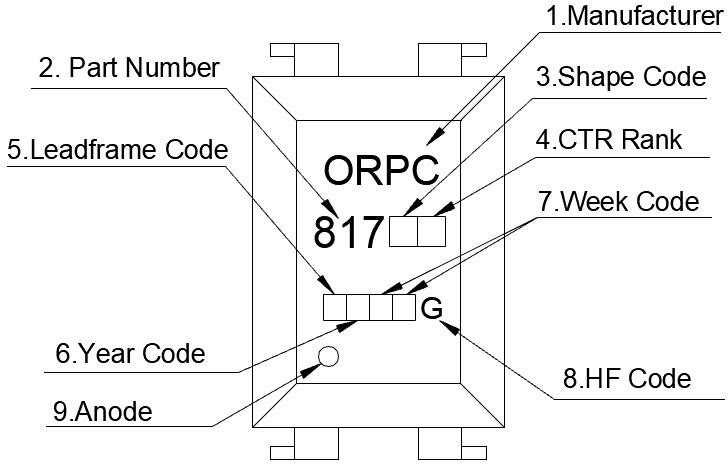
- Manufacturer : ORIENT.
- Part Number : 817.
- Shape Code
 (M , or none) .
 - Rank Code : CTR Rank
- Lead frame Code :‘F’ means Iron.
- Year Code : '1' means '2021' and so on.
- Week Code
 : 01 means the first week, 02 means the second week and so on.
 - HF Identification ‘G’ .
- Anode.
Package dimension
DIP Type
|
Packing Information |
|
|
Packing type |
Tube |
|
Qty per Tube |
100pcs |
|
Small box (Inner) Dimension |
525*128*60mm |
|
Large box (Outer) Dimension |
545*290*335mm |
|
The Amount per Inner Box |
5,000pcs |
|
The Amount per Outer Box |
50,000pcs |
Packing Label Sample
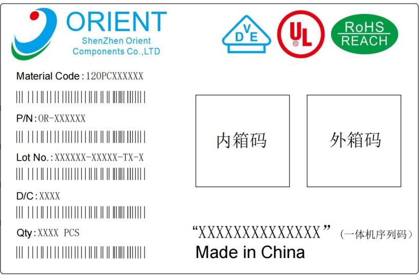 Note:
Note:
-
- Material Code :Product ID.
- P/N :Contents with "Order Information" in the specification.
- Lot No. :Product data.
- D/C :Product weeks.
- Quantity :Packaging quantity.
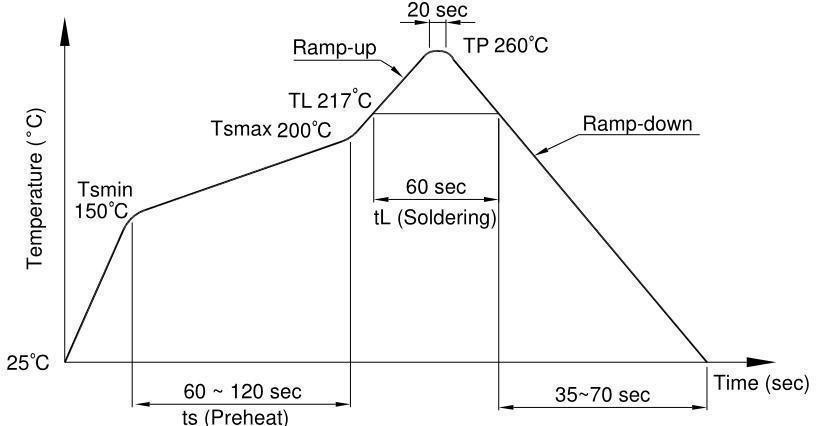
Temperature Profile Of Soldering
(1).IR Reflow soldering (JEDEC-STD-020C compliant)
One time soldering reflow is recommended within the condition of temperature and time profile shown below. Do not solder more than three times.
|
Profile item |
Conditions |
|
Preheat
- Time (min to max) (ts) |
150˚C 200˚C 90±30 sec |
|
Soldering zone - Temperature (TL ) - Time (t L ) |
217˚C 60 sec |
|
Peak Temperature |
260˚C |
|
Peak Temperature time |
20 sec |
|
Ramp-up rate |
3˚C / sec max. |
|
Ramp-down rate from peak temperature |
3~6˚C / sec |
|
Reflow times |
≤3 |
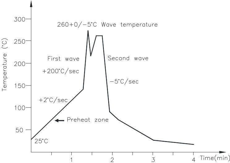
(2).Wave soldering (JEDEC22A111 compliant)
One time soldering is recommended within the condition of temperature.
|
Temperature Time |
260+0/-5˚C 10 sec |
|
Preheat temperature Preheat time |
25 to 140˚C 30 to 80 sec |
(3).Hand soldering by soldering iron
Allow single lead soldering in every single process. One time soldering is recommended.
Temperature
380+0/-5˚C
Time
3 sec max


")
