English
 English
 Español
 Português
 русский
 français
 日本語
日本語 Deutsch
 Tiếng Việt
 Italiano
 Nederlands
 ไทย
ไทย Polski
 한국어
한국어 Svenska
 magyar
 Malay
Malay বাংলা
বাংলা Dansk
Dansk Suomi
Suomi हिन्दी
 Pilipino
 Türk
Türk Gaeilge
 عربى
عربى Indonesia
 norsk
norsk Burmese
 български
 ລາວ
ລາວ Latine
 Қазақ
Қазақ Euskal
 Azərbaycan
 slovenský
 Македонски
 Română
 Slovenski
 Српски
 Afrikaans
 Беларус
 Hrvatski
 Монгол хэл
 Zulu
Zulu Somali
 O'zbek
 Hawaiian

 Consume Grade Phototransistor Optocoupler OR-3H7-EN-V13
 Consume Grade Phototransistor Optocoupler OR-3H7-4-EN-V3
 Consume Grade Phototransistor Optocoupler OR-3H4-EN-V12
 Consume Grade Phototransistor Optocoupler OR-3H4-4-EN-V3
 Consume Grade Phototransistor Optocoupler ORPC-817-S-(SJ)
- Consume Grade Phototransistor Optocoupler ORPC-817-S-(SJ)-EN-V0
- All new products


Darlington Optocoupler OR-3H5-EN-V4
Current transfer ratio (CTR) : 600% Min. at IF = 1mA, VCE = 2V
Product Description
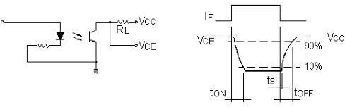
High speed optocouple
Features
- Current transfer ratio (CTR) : 600% Min. at IF = 1mA, VCE = 2V
- High input-output isolation voltage.(VISO=3,750Vrms)
- Employs double transfer mold technology
- Operating temperature:-55℃ to 100℃
- Safety approval
- UL approved(No.E323844)
- VDE approved(No.40029733)
CQC approved (No.CQC19001231256) - In compliance with RoHS, REACH standards
- MSL Level 1
Instructions
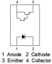
The OR-3H5 series device contains an infrared emitting diodes, optically to a photo Darington detector.
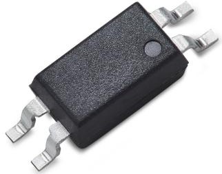
They are encapsulated in a 4-pin SSOP, free of halogens and Sb2O3
Application Range
-
-
Hybrid substrates that require high density mounting
-
Programmable controller
-
Max Absolute rated Value (Normal Temperature=25℃)
|
Parameter |
Symbol |
Rated Value |
Unit |
|
|
Input |
Forward Current |
IF |
50 |
mA |
|
Peak forward current(t=10us) |
IFM |
1 |
A |
|
|
Reverse Voltage |
VR |
6 |
V |
|
|
Power Dissipation |
P |
100 |
mW |
|
|
Junction Temperature |
TJ |
125 |
℃ |
|
|
Output |
Collector and emitter Voltage |
VCEO |
40 |
V |
|
Emitter and collector Voltage |
VECO |
7 |
||
|
Collector Current |
IC |
90 |
mA |
|
|
Power Dissipation |
PC |
150 |
mW |
|
|
Junction Temperature |
TJ |
125 |
℃ |
|
|
*1 Insulation Voltage |
Viso |
3750 |
Vrms |
|
|
Operating Temperature |
Topr |
-55 to +100 |
℃ |
|
|
Storage Temperature |
Tstg |
-55 to +150 |
||
|
*2 Soldering Temperature |
Tsol |
260 |
||
*1. AC For 1 Minute, R.H. = 40 ~ 60%
Isolation voltage shall be measured using the following method.
-
Short between anode and cathode on the primary side and between collector and emitter on the secondary side.
-
The isolation voltage tester with zero-cross circuit shall be used.
-
The waveform of applied voltage shall be a sine wave.
*2.soldering time is 10 seconds.
Opto-electronic Characteristics(Normal Temperature=25℃)
|
Parameter |
Symbol |
Min |
Typ.* |
Max |
Unit |
Condition |
|
|
Input |
Forward Voltage |
VF |
--- |
1.1 |
1.4 |
V |
IF=5mA |
|
Reverse Current |
IR |
--- |
--- |
5 |
µA |
VR =5V |
|
|
Terminal Capacitance |
Ct |
--- |
30 |
250 |
pF |
V=0, f=1KHz |
|
|
Output |
Collector Dark Current |
ICEO |
--- |
--- |
400 |
nA |
VCE=40V,IF=0 |
|
Collector-Emitter Breakdown Voltage |
BVCEO |
40 |
--- |
--- |
V |
IC=0.1mA IF=0 |
|
|
Emitter-Collector Breakdown Voltage |
BVECO |
7 |
--- |
--- |
V |
IE=0.1mA IF=0 |
|
|
Transforming Characteristics |
Current Transfer Ratio |
CTR |
600 |
--- |
7500 |
% |
IF=1mA VCE =2V |
|
Collector Current |
IC |
6 |
--- |
75 |
mA |
||
|
Collector-Emitter Saturation Voltage |
VCE(sat) |
--- |
--- |
1 |
V |
IF=1mA IC= 2mA |
|
|
Insulation Impedance |
Riso |
5×10¹⁰ |
1×10¹¹ |
--- |
Ω |
DC500V 40~60%R.H. |
|
|
Floating Capacitance |
Cf |
--- |
0.6 |
1 |
pF |
V=0, f=1MHz |
|
|
Response Time(Rise) |
tr |
--- |
200 |
--- |
μs |
VCc=5V, IC=2mA RL=100Ω |
|
|
Descend Time(fall) |
tf |
--- |
200 |
--- |
μs |
||
-
Current Conversion Ratio = IC / IF × 100%
Rank table of current transfer ratio CTR
|
MODEL NO. |
CTR Rank |
Min. |
Max. |
Unit |
Condition |
|
OR-3H5 |
NO mark |
600 |
--- |
% |
IF=1mA, VCE=2V, Ta=25℃ |
-
Current Conversion Ratio = IC / IF × 100%
Order Information
Part Number
OR-3H5-X-Y-Z
Note
X = Tape and reel option (TP or TP1).
Y = ‘V’ code for VDE safety (This options is not necessary). Z = ‘G’ code for Halogen free.
* VDE Code can be selected.
|
Option |
Description |
Packing quantity |
|
TP |
Surface mount lead form (low profile) + TP tape & reel option |
3000 units per reel |
|
TP1 |
Surface mount lead form (low profile) + TP1 tape & reel option |
3000 units per reel |
Naming Rule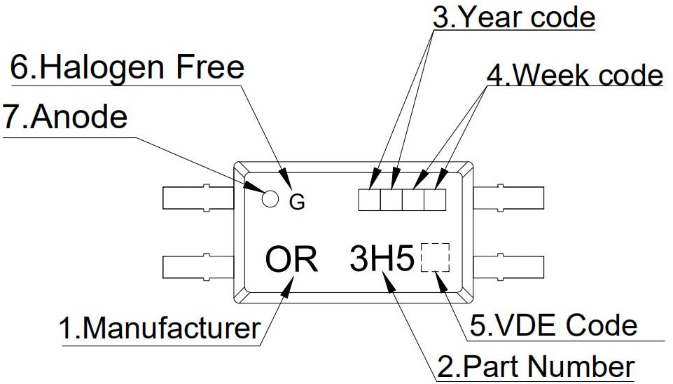
-
Manufacturer : ORIENT.
-
Part Number : 3H5.
-
Year Code
 : '21' means '2021' and so on.
 -
Week Code
: 01 means the first week, 02 means the second week and so on. -
VDE Code
 . (Optional)
 -
HF Code ‘G’: Halogen Free.
-
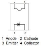
Anode.
- VDE Mark can be selected.
Outer Dimension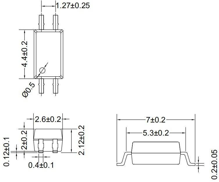
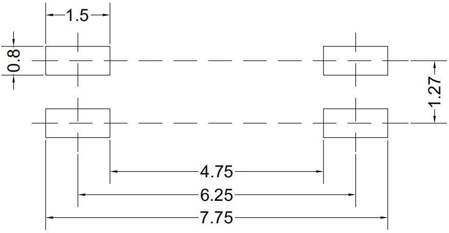
Recommended Foot Print Patterns (Mount Pad) (unit:mm)
Taping Dimensions
OR-3H5-TP
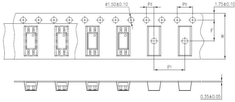
OR-3H5-TP1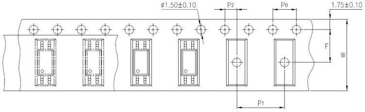
|
type |
Symbol |
Dimensions: mm (in.) |
|
bandwidth |
W |
12±0.3 (0.47) |
|
pitch |
P0 |
4±0.1 (0.15) |
|
pitch |
F |
5.5±0.1 (0.217) |
|
P2 |
2±0.1 (0.079) |
|
|
interval |
P1 |
8±0.1 (0.315) |
|
Encapsulation type |
TP/TP1 |
|
Quantity (pieces) |
3000 |
package dimension
|
Packing Information |
|
|
Packing type |
Reel type |
|
Tape Width |
12mm |
|
Qty per Reel |
3,000pcs |
|
Small box (inner) Dimension |
345*345*45mm |
|
Large box (Outer) Dimension |
480x360x360mm |
|
Max qty per small box |
6,000pcs |
|
Max qty per large box |
60,000pcs |
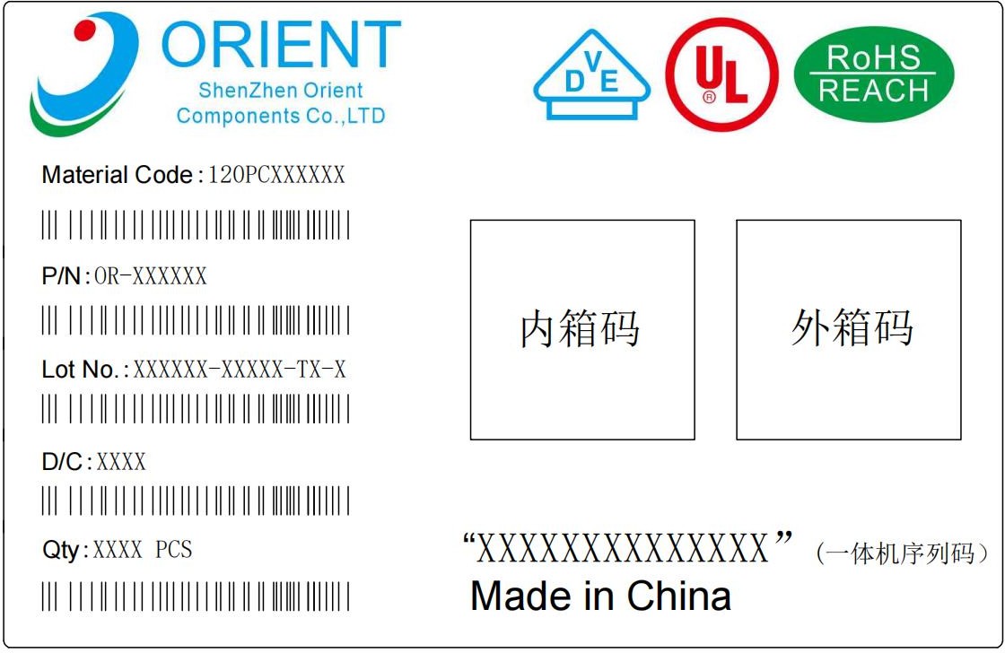
Packing Label Sample
Note:
-
Material Code :Product ID.
-
P/N :Contents with "Order Information" in the specification.
-
Lot No. :Product data.
-
D/C :Product weeks.
-
Quantity :Packaging quantity.
Reliability Test
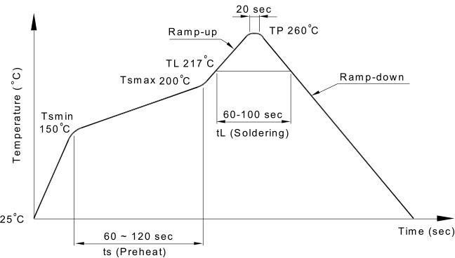
Temperature Profile Of Soldering
IR Reflow soldering (JEDEC-STD-020C compliant)
Note: onesolderbackflowisrecommendedundertheconditionsdescribedbelowinthe temperature and time profile. Do not weld more than three times.
|
Profile item |
Conditions |
|
Preheat
- Time (min to max) (ts) |
150˚C |
|
Soldering zone |
217˚C |
|
Peak Temperature |
260˚C |
|
Peak Temperature time |
20 sec |
|
Ramp-up rate |
3˚C / sec max. |
|
Ramp-down rate from peak temperature |
3~6˚C / sec |
|
Reflow times |
≤3 |
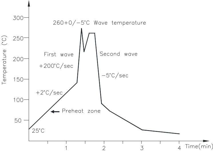
Wave soldering (JEDEC22A111 compliant)
One-time welding is recommended under the temperature condition.
|
Temperature |
260+0/-5˚C |
|
Preheat temperature Preheat time |
5 to 140˚C |
Hand soldering by soldering iron
Single lead welding is allowed in each process and one-time welding is recommended.
Temperature
380+0/-5˚C
Time
3 sec max
Characteristics Curve