English
 English
 Español
 Português
 русский
 français
 日本語
日本語 Deutsch
 Tiếng Việt
 Italiano
 Nederlands
 ไทย
ไทย Polski
 한국어
한국어 Svenska
 magyar
 Malay
Malay বাংলা
বাংলা Dansk
Dansk Suomi
Suomi हिन्दी
 Pilipino
 Türk
Türk Gaeilge
 عربى
عربى Indonesia
 norsk
norsk Burmese
 български
 ລາວ
ລາວ Latine
 Қазақ
Қазақ Euskal
 Azərbaycan
 slovenský
 Македонски
 Română
 Slovenski
 Српски
 Afrikaans
 Беларус
 Hrvatski
 Монгол хэл
 Zulu
Zulu Somali
 O'zbek
 Hawaiian

 Consume Grade Phototransistor Optocoupler OR-3H7-EN-V13
 Consume Grade Phototransistor Optocoupler OR-3H7-4-EN-V3
 Consume Grade Phototransistor Optocoupler OR-3H4-EN-V12
 Consume Grade Phototransistor Optocoupler OR-3H4-4-EN-V3
 Consume Grade Phototransistor Optocoupler ORPC-817-S-(SJ)
- Consume Grade Phototransistor Optocoupler ORPC-817-S-(SJ)-EN-V0
- All new products


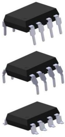
Darlington Optocoupler ORPC-825-EN-V1
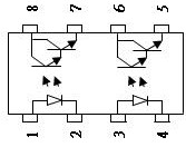
The ORPC-825 series devices each consists of an infrared emitting diodes, optically coupled to a Darlington phototransistor detector.These devices are packaged in an 8-pin DIP package and available in wide-lead spacing and SMD option.
Product Description
high-speed isolation op-amp optocoupler
Features
- Current transfer ratio(CTR: 600~7500% at IF = 1 mA, Vce = 2 V)
- High isolation voltage between input and output (Viso = 5000 V rms )
- Creepage distance > 7.62 mm
- Operating temperature up to + 110°C
- Compact small outline package
- The product itself will remain within RoHS compliant version
- Safety approval
- UL approved(No.E323844) VDE approved (No.40029733)
- CQC approved (No.CQC19001231254)
- In compliance with RoHS, REACH standards
- MSL Class Ⅰ
Instructions
-
The ORPC-825 series devices each consists of an infrared emitting diodes, optically coupled to a Darlington phototransistor detector.These devices are packaged in an 8-pin DIP package and available in wide-lead spacing and SMD option.
-
Pin pitch of ORPC-825 is 2.54mm
Application Range
-
-
Telephone set, telephone exchangers
-
Sequence controllers
-
System appliances, measuring instruments
-
Signal transmission between circuits of different potentials and impedances
-
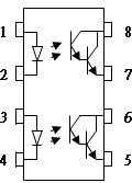
Pin Configuration 1,3. Anode
2, 4. Cathode
5.7. Emitter
6.8. Collector
Absolute Maximum Ratings (Ta=25℃)
|
Parameter |
Symbol |
Rated Value |
Unit |
|
|
Input |
Forward Current |
IF |
60 |
mA |
|
Peak forward Current(1us pulse) |
IFP |
1 |
A |
|
|
Reverse Voltage |
VR |
6 |
V |
|
|
Consume Power |
P |
100 |
mW |
|
|
Output |
Collector and emitter Voltage |
VCEO |
40 |
V |
|
Emitter and collector Voltage |
VECO |
7 |
||
|
Collector Current |
IC |
80 |
mA |
|
|
Consume Power |
PC |
150 |
mW |
|
|
Total Consume Power |
Ptot |
200 |
mW |
|
|
*1 Insulation Voltage |
Viso |
5,000 |
Vrms |
|
|
Rated Impulse Insulation Voltage |
VIORM |
630 |
V |
|
|
Working Temperature |
Topr |
-55 to + 110 |
℃ |
|
|
Deposit Temperature |
Tstg |
-55 to + 125 |
||
|
*2 Soldering Temperature |
Tsol |
260 |
||
*1. AC Test, 1 minute, humidity = 40~60%
Isolation voltage shall be measured using the following method.
-
-
Short between anode and cathode on the primary side and between collector and emitter on the secondary side.
-
The isolation voltage tester with zero-cross circuit shall beused.
-
The waveform of applied voltage shall be a sine wave.
-
*2. soldering time is 10 seconds
Electrical optical characteristics at TA=25℃
|
Parameter |
Symbol |
Min |
Typ.* |
Max |
Unit |
Condition |
|
|
Input |
Forward Voltage |
VF |
--- |
1.2 |
1.4 |
V |
IF=20mA |
|
Reverse Current |
IR |
--- |
--- |
5 |
μA |
VR=5V |
|
|
Collector Capacitance |
Ct |
--- |
30 |
250 |
pF |
V=0, f=1KHz |
|
|
Output |
Collector to Emitter Current |
ICEO |
--- |
--- |
1 |
uA |
VCE=10V, IF=0mA |
|
Collector and Emitter attenuation Voltage |
BVCEO |
40 |
--- |
--- |
V |
IC=0.1mA IF=0mA |
|
|
Emitter and Collector attenuation Voltage |
BVECO |
7 |
--- |
--- |
V |
IE=0.1mA IF=0mA |
|
|
*1 Current conversion ratio |
CTR |
600 |
--- |
7500 |
% |
||
|
IF=1mA |
|||||||
|
Transfo rming |
Collector Current |
IC |
6 |
--- |
75 |
mA |
VCE=2V |
|
Charact eristics |
Collector and Emitter Saturation Voltage |
VCE(sat) |
--- |
0.8 |
1 |
V |
IF=20mA IC= 5mA |
|
Insulation Impedance |
Riso |
5×10¹⁰ |
1×10¹² |
--- |
Ω |
DC500V 40~60%R.H. |
|
|
Floating Capacitance |
Cf |
--- |
0.6 |
1.0 |
pF |
V=0, f=1MHz |
|
|
Cut-off Frequency |
fc |
1 |
6 |
--- |
kHz |
VCE=5V, IC=2mA RL=100Ω, -3dB |
|
|
Rise Time |
tr |
--- |
60 |
300 |
μs |
VCE=2V, |
|
|
IC=10mA |
|||||||
|
Descend Time |
tf |
--- |
53 |
250 |
μs |
RL=100Ω |
|
*1 Current Conversion Ratio = IC / IF × 100%
Order Information
Part Number
ORPC-825T-W-X-Y-Z
Note
T = Lead form option (S, M or none)
W = Tape and reel option (TP,TP1 or none). X = Lead frame option (F: Iron, C:copper)
Y = ‘V’ code for VDE safety (This options is not necessary).
Z = ‘G’ code for Halogen free (This options is not necessary).
-
VDE Code can be selected.
-
Halogen Free can be selected.
|
Option |
Description |
Packing quantity |
|
None |
Standard DIP-8 |
45 units per tube |
|
M |
Wide lead bend (0.4 inch spacing) |
45 units per tube |
|
S(TA) |
Surface mount lead form (low profile) + TA tape & reel option |
1000 units per reel |
|
S(TA1) |
Surface mount lead form (low profile) + TA1 tape & reel option |
1000 units per reel |
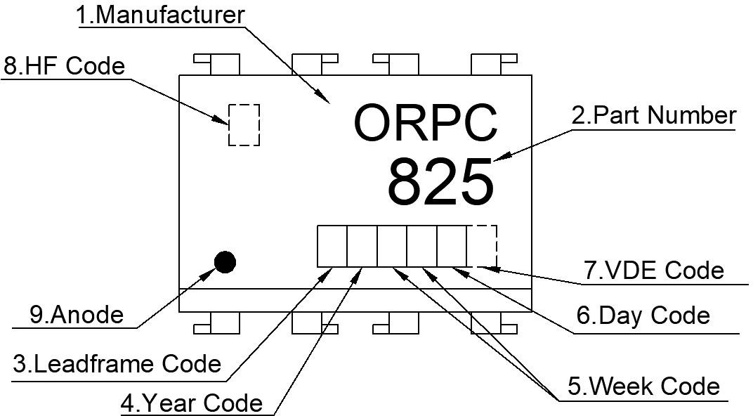
Naming Rule
-
-
Manufacturer : ORIENT.
-
825 denotes Part Number.
-
Lead frame Code
 :‘F’ means Iron,‘C’ means Copper.
 -
Year Code
: '1' means '2021' and so on. -
Week Code
 : 01 means the first week, 02 means the second week and so on.
 -
Day Code
:“A to G” means “Monday to Sunday” -
VDE Code
 . (Optional)
 -
HF Code
:Halogen Free. (Optional) -
Anode.
-
Halogen Free Mark can be selected.
-
VDE Mark can be selected.
-
-
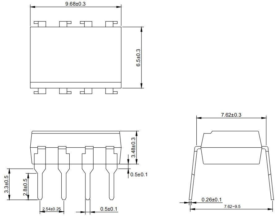
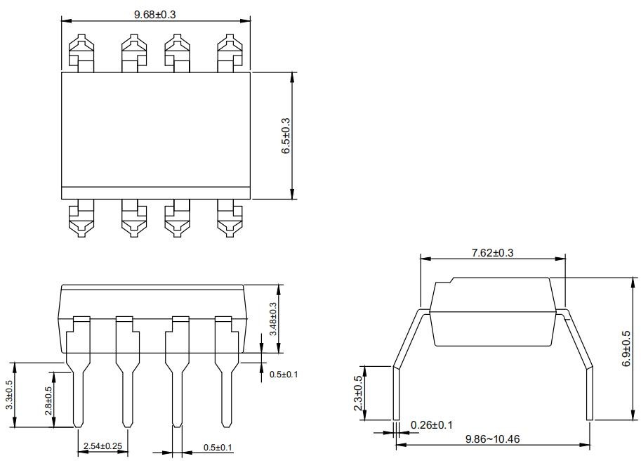
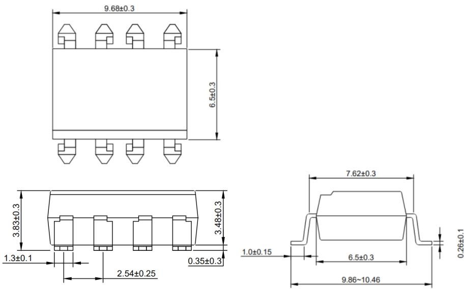
Outer Dimension ( Unit:mm)
-
ORPC-825
-
ORPC-825M
-
ORPC-825S
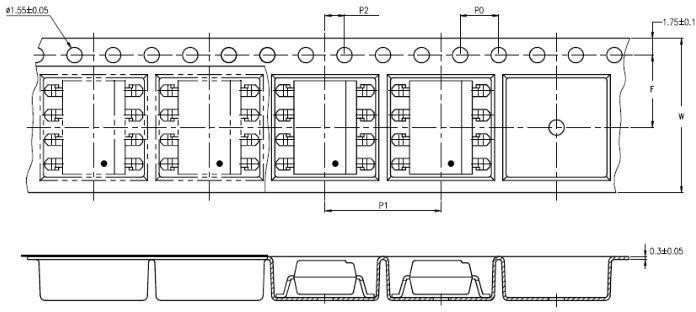
Taping Dimensions
-
ORPC-825S-TA
-
ORPC-825S-TA1
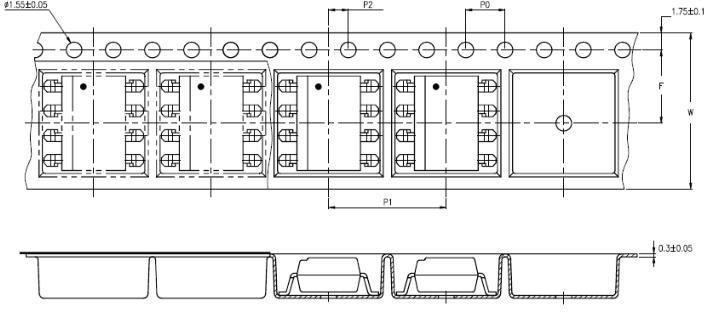
|
Description |
Symbol |
Dimension in mm(inch) |
|
Tape wide |
W |
16±0.3(0.63) |
|
Pitch of sprocket holes |
P0 |
4±0.1(0.15) |
|
Distance of compartment |
F |
7.5±0.1(0.295) |
|
P2 |
2±0.1(0.079) |
|
|
Distance of compartment to compartment |
P1 |
12±0.1(0.472) |
|
Package Type |
TA/TA1 |
|
Quantities(pcs) |
1000 |
package dimension
DIP Type
|
Packing Information |
|
|
Packing type |
Tube |
|
Qty per Tube |
45pcs |
|
Small box (Inner) Dimension |
525*128*60mm |
|
Large box (Outer) Dimension |
545*290*335mm |
|
The Amount per Inner Box |
2,250pcs |
|
The Amount per Outer Box |
22,500pcs |
SOP Type
|
Packing Information |
|
|
Packing type |
Reel type |
|
Tape Width |
16mm |
|
Qty per Reel |
1,000pcs |
|
Small box (inner) Dimension |
345*345*58.5mm |
|
Large box (Outer) Dimension |
620x360x360mm |
|
Max qty per small box |
2,000pcs |
|
Max qty per large box |
20,000pcs |
Packing Label Sample

Note:
-
Material Code :Product ID.
-
P/N :Contents with "Order Information" in the specification.
-
Lot No. :Product data.
-
D/C :Product weeks.
-
Quantity :Packaging quantity.
Reliability Test
-
Temperature Profile Of Soldering
-
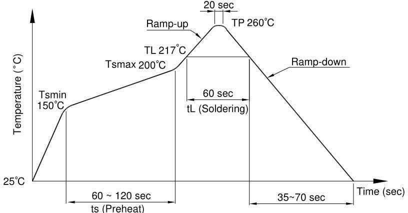
IR Reflow soldering (JEDEC-STD-020C compliant)
One time soldering reflow is recommended within the condition of temperature and time profile shown below. Do not solder more than three times.
|
Profile item |
Conditions |
|
Preheat
- Time (min to max) (ts) |
150˚C 200˚C 90±30 sec |
|
Soldering zone - Temperature (TL ) - Time (t L ) |
217˚C 60 sec |
|
Peak Temperature |
260˚C |
|
Peak Temperature time |
20 sec |
|
Ramp-up rate |
3˚C / sec max. |
|
Ramp-down rate from peak temperature |
3~6˚C / sec |
|
Reflow times |
≤3 |
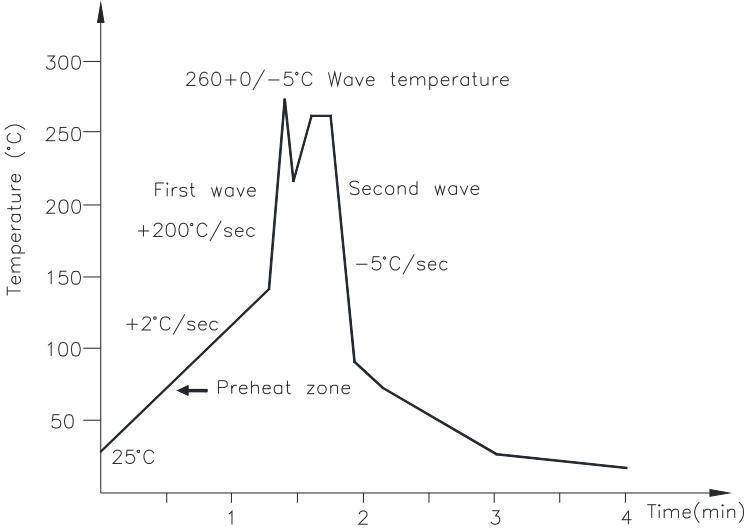
Wave soldering (JEDEC22A111 compliant
One time soldering is recommended within the condition of temperature.
|
Temperature Time |
260+0/-5˚C 10 sec |
|
Preheat temperature Preheat time |
5 to 140˚C 30 to 80 sec |
Hand soldering by soldering iron
Allow single lead soldering in every single process. One time soldering is recommended.
3 sec max
380+0/-5˚C
Time
Temperature


